|
|
|
|
|
|
|
|
|
|


![]()
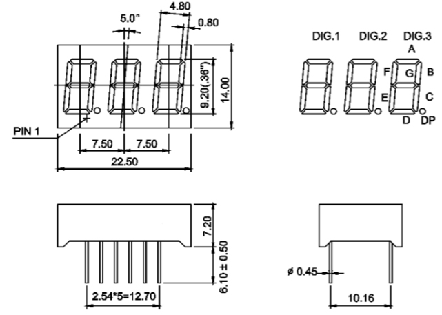
LCT-3632TW11: Three Digit
White 0.36 Inch (9.14mm) LED Anode
|
PRODUCT DESCRIPTION |
|
|
(1) Three Digit
0.36 Inch (9.14mm) Height |
(5) Black color background |
|
(2) Low current
operation |
(6) Common Anode |
|
(3) Excellent
color and font characteristics |
(7) RoHs Compliant Part |
|
(4) Colors: White, blue, red, yellow and green |
|
Absolute Maximum
Rating (Ta = 250C)
|
PARAMETER |
MAXIMUM RATING |
UNITS |
|
Power Dissipation per Segment |
40 |
mW |
|
DC Forward Current per Segment |
20 |
mA |
|
Reverse Voltage per Segment (IR
= 10mA) |
5 |
V |
|
Peak Pulse Forward Current per Segment (1) |
100 |
mA |
|
Operating Temperature |
-25
to +80 |
0C |
|
Storage Temperature |
-40
to +85 |
0C |
(1) Pulse conditions of 1/10 duty and 0.1msec
width, for long operating life, max. of 20mA recommended
(2) Solder
Temperature of 1/16” Below Seating Plane for 5 Seconds at 2600C
Electro-optical
Characteristics (Ta = 250C)
|
PARAMETER |
SYMBOL |
CONDITIONS |
MIN. |
TYP. |
MAX. |
UNIT |
|
Forward Voltage per Segment |
VF |
IF
= 20mA |
3.3 |
|
3.8 |
V |
|
Reverse Current per Segment |
IR |
VR = 5V |
|
|
10 |
mA |
|
Chromaticity Coordinate |
x |
IF
= 20mA |
|
0.29 |
|
|
|
y |
IF
= 20mA |
|
0.30 |
|
|
|
|
Luminous Intensity |
IV |
IF
= 20mA |
60 |
75 |
|
mcd |
|
Luminous Intensity Matching Ratio |
Iv-m |
IF
= 20mA |
2:1 |
|||
DEVICE
DIAGRAM
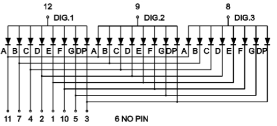
INTERNAL
CIRCUIT LAYOUT
![]()
![]()
|
LC LED Corporation |