|
|
|
|
|
|
|
|
|
|


![]()
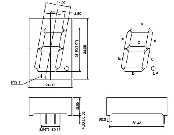
LCS-10010TB1C: Single Digit
Blue 1.0 Inch (24 x 34mm) Cathode Display
|
PRODUCT DESCRIPTION |
|
|
(1) 1.0 Inch
(25.40mm) Digit Height |
(5) Black color background |
|
(2) Low current
operation |
(6) Common Cathode |
|
(3) Excellent color
and font characteristics |
(7) RoHs Compliant Part |
|
(4) Colors: White, blue, red, yellow and green |
|
Absolute Maximum Rating
(Ta = 250C)
|
PARAMETER |
RED |
AMBER |
GREEN |
BLUE |
WHITE |
UNITS |
|
DC Forward
Current Per Segment |
30 |
30 |
25 |
30 |
20 |
mA |
|
Peak Current
Per Segment (1) |
70 |
50 |
50 |
25 |
25 |
mA |
|
Avg. Forward
Current (Pulse Operation) Per Segment |
30 |
30 |
25 |
25 |
25 |
mA |
|
Derating
Linear From 250C Per Segment |
0.3 |
mA/0C |
||||
|
Reverse
Voltage (2) |
3 |
V |
||||
|
Operating
Temperature |
-25
to +85 |
0C |
||||
|
Storage Temperature |
-30
to +85 |
0C |
||||
(1) Pulse conditions of 1/10 duty and 0.1msec
width, for long operating life, max. of 20mA recommended
(2) Reverse
biasing is not recommended, will cause damage
Electro-optical
Characteristics (Ta = 250C)
|
|
|
|
MAX. |
|
|
LUMINOUS INTENSITY |
|
LCS-10010TUR1C |
AlInGaP |
630 |
10 |
3.6
(1) |
4.2 |
80,000
ucd |
|
LCS-10010TB1C |
InGaN |
468 |
10 |
6.0
(2) |
7.0 |
85,000
ucd |
|
LCS-10010YG1C |
AlInGaP |
568 |
10 |
3.6
(1) |
4.2 |
75,000
ucd |
|
LCS-10010UY1C |
AlInGaP |
590 |
10 |
3.6
(1) |
4.2 |
75,000
ucd |
|
LCS-10010TW1C |
InGaN |
5,500K |
10 |
6.0
(2) |
7.0 |
100,000
ucd |
PIN
MAPPING TABLE
|
PIN NO. |
|
|
|
|
1 |
Anode E |
6 |
Anode B |
|
2 |
Anode D |
7 |
Anode A |
|
3 |
Common Cathode PIN |
8 |
Common Cathode PIN |
|
4 |
Anode C |
9 |
Anode F |
|
5 |
Anode DP (1) |
10 |
Anode G |
(1)
Anode DP Vf = 1.8V ONLY uses one led
chip for red, yellow and green color.
(2)
Anode DP Vf = 3.3V ONLY uses one led
chip for blue and white color.
DEVICE
DIAGRAM
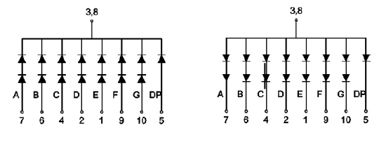
![]()
|
LC LED Corporation |